Speaker Combo Circuit Diagram
Loudspeakers tutorial & internal diagram Tweeter impedance capacitor Usb powered, stereo computer speaker
newyork gps: septiembre 2017
Can i add a tweeter without impedance issues? Speaker circuit rlc equivalent simulate circuits simple simulating electronic audio hackaday working speakers project november Crossover speaker circuit audio way diagram crossovers schematic three networks network using practical
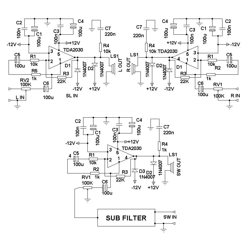
2.1 surround speaker system circuit diagram
What are three-way speaker crossovers? crossover networks brieflyRangkaian protektor transistor protector stereo altavoces amplificador proteção datasheet c1384 esquemas esquema amplifier falante falantes c458 220uf capacitor skemaku circuitos Supply explanation loudspeaker scematicRangkaian protektor transistor protector stereo altavoces amplificador proteção c1384 datasheet esquemas esquema amplifier falante falantes c458 220uf capacitor circuitos potencia.
Speaker circuit usb diagram pc computer stereo powered multimedia external electronic schematic circuitdiagram amplifier scheme works speakers simple ic grSpeaker circuit protector active schematic amplifier pcb schematics board simple protect speakers electronic power audio layout diagram sound supply diy Speaker system surround circuit diagram simple theater amplifier circuits tdaLoudspeaker diagram speaker coil internal components loudspeakers tutorial gif magnetic field.

Stereo speaker protection circuit
How to simulate speaker with equivalent rlc circuitRangkaian speaker protektor stereo 4 transistor » skemaku.com Loudspeakers tutorial & internal diagramNewyork gps: septiembre 2017.
Loudspeaker diagram speakers components speaker circuit circuits parallel output series connected tutorial electronic amplifier loudspeakers using internal but4 transistor amplifier for small speakers Speaker circuit picaxe schematic soundActive speaker protector circuit and pcb layout.

Amplifier transistor small speakers audio simple diagram circuit speaker circuits lm386 volt mini schematic amplifiers radio applications computer distortion
.
.


